A proa for Ariadne

30 November 2009     Editor    9 Comments.

Maestro proa designer John Dalziel has an interesting new project - an 8m proa “workhorse” for the Greek Isles.

On the Greek island of Naxos, fabled home of Dionysus and Ariadne, Helmut Mueller is building an 8 meter proa. Unusually for its size, it is actually a half-displacement model of a 10 meter proa Helmut intends to build. However, we decided it was best to build the 8 meter model first and test it thoroughly. Besides being a lot of fun, the 10 M proa is intended to be practical transportation between the islands of the Cyclades, with the ability to carry several hundred kg of cargo- so it needs to work, and work well.

This proa is laid out along the general lines of the Kiribati proas, with the famous “Kiribati dimple” in the lee side, and a 40 mm lateral camber to the keel. The only hydrodynamic innovation is the use of a “vortex tunnel” keel, which Dieter Shulz and John Dalziel developed some years ago, to get better windward speed from hulls without daggerboards. Dieter built and tested aerodynamic models which showed promising lift/drag characteristics, but as far as we know this will be the first full-size test of the concept.

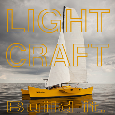
The 25sm crab-claw sail is actually intended for the 10 M boat, but we are using it on the 8 M model to make sure a crew of one or two can handle it safely. If all goes well, this will be quite a fast proa.

After aeronautical engineer Janusz Ostrowski calculated the weight of wood spars for the boat, we decided to “bite the bullet” and build them from carbon fiber; handling the weight of the wood spars would quickly tire out the crew. Carbon should solve that problem, but I think we are near the practical limits for a crab-claw sail on a boat sailed by only two crew.

Helmut intends to experiment with rigs, including a mast step location to windward on a girder (shown on the three-view) or in the traditional position, plus the use of a lee shroud or a bungee-loaded back-wind brace. There is a step and partners fitted to the main hull that will allow the use of a free-standing mast. It is also possible to mount a marconi rig on the mast girder, in the manner of Russ Brown’s proas.

Helmut plans to use Gary Dierking’s bungee- assisted shunting system, and will test shunting using a free yard, a continuous shunting line, and if necessary, a full-length track-and-car system on deck. Spilling lines are used for sail control.

To avoid the usual problems with steering, we went with the tried-and-true long sweep. The sweep can be used on either side of the stern, though we intend at first to use Gary Dierking’s system on the windward side. There is a lot of extra reinforcement in the ends, to allow testing of quarter-rudders or leeboards.

Non-steering daggerboards and slots are built into the hull at either end; these will take the strain off the helmsman when sailing downwind, and will also allow the boat to be balanced when the Western-style rigs are tested.

There is a 255 liter water-ballast tank located in the ama, but design 75/25 weight distribution is achieved with only 80 liters of water. There are two pumps located at the cockpit to fill or drain the tank.

One trick we will try is to make the lee pod do double-duty as a dinghy. This is an old idea with several major problems, but we are going to see if we can make it work. The fixed pod of the 10 M proa is designed to right the boat from a static heel to leeward of 110 degrees. We won’t achieve such a deep angle with the dinghy-pod, but we will get self-righting to at least 100 degrees.

Specifications

  • LOA- 8 M (26’4”)
  • LWL- 7.518 M
  • Ama LOA- 4.96 M
  • Ama LWL- 4.82 M
  • Beam Overall- 5.401 M
  • Beam Hull- 0.883 M
  • Hull BWL- 0.407 M
  • Beam, Hull C/L to Ama C/L- 4.16 M
  • Beam Ama- 0.377 M
  • Ama BWL- 0.293 M
  • Hull Draft- 0.488 M
  • Ama Draft- 0.29 M
  • Aka Clearance over flat water- 0.803 M
  • Design Displacement, fully loaded, with crew, all equipment, and 80 liters water ballast- 640 kg
  • Ama Water Ballast Capacity- 255 kg
  • Design weight distribution- hull 75%, ama 25%
  • Wt. dist, no water ballast- hull 85%, ama 15%
  • Wt. dist, full water ballast- hull 60%, ama 40%
  • Sail Area- 25 M2 (269 sq. ft.)
  • Mast Length- 7-8 M
  • Yard and Boom Length- 8.3 M

Design Credits

Overall concept, lines, general layout: John Dalziel
Construction design and methods: Helmut Mueller
Sail plan, spars and carbon fiber specifications: Janusz Ostrowski

 Reports  New Designs  Boatbuilding  Proas

9 Comments

Make a Comment


  • Hello All!
    I am new to this exciting world of exotic Proa craft and am
    learning as much as I can.  I have two questions that I hope
    someone can respond to as I may not be the only person curious
    about learning the answers to these:

    1. ““Kiribati dimple” in the lee side, and a 40 mm lateral camber to
    the keel.” 
    Question: Is the lee side “dimple” the natural consequence of the
    40mm camber to the keel?  Or is it deeper? Seeking a better mental
    model of what is intended and been found practically useful.
    I have found this reference which describes this implementation
    in traditional Kiribti canoe fabrication:
    http://clacabanne.free.fr/construction_bateaux.htm

    2. Question: How can I learn more about: “the use of a “vortex
    tunnel” keel, which Dieter Shulz and John Dalziel developed some
    years ago”?  I understand that some boats shed a vortex trail. I do
    not yet understand the concept for a “vortex tunnel keel”.

    2024-02-16 13:50 | by Michael McDowell

    • Hello Michael, Thanks for the link to that very good web page. I’ll use it in trying to answer your questions. Yes, the “Kiribati dimple” is mainly a consequence of the horizontal displacement of the keel. If you look on that web page at figure #6, which is correctly drawn, you’ll see that the keel line descends in an almost straight line from the stems, then makes a fairly abrupt curve right at the centerline. For a canoe the size of the ones in the topmost illustration, this curve will be less than one meter long. When the “set” of the lateral curve is done correctly (Fig # 3), it will take a very similar shape, with mainly straight lines from the stems to the short middle curve. So the keel curve in either case is not a smooth arc from bow to “stern,” it is (mostly) straight lines connected by a short curve at the middle. The purpose of this is subtle; a keel of this type uses vortex lift to create lateral resistance. As shown in Fig #7, the tip of the keel needs to be pretty sharp for this to work efficiently. There are two main types of vortexes, the “bound vortex” and the “free vortex.” The free vortex does nothing good for you, and creates lots of drag, so you definitely want the bound vortex, which will run only along the descending line of the keel, very close to the hull planking on the windward side, from the cutwater back to near the centerline, where the vortex will jump off the hull at an angle away from the canoe’s direction of travel (and become a free vortex). The larger the angle of the jump, the greater the drag. The sharper lateral curve in the keel at the centerline line creates a small zone of higher pressure water on the lee side of the keel, which energizes the water flow over the bottom of the keel, allowing the vortex to remain bound for just a little longer, so it jumps off the keel at a smaller angle to the direction of travel- creating less drag. Note in Fig #7 that as drawn, there is less displacement on the lee side of the keel; this is correct, but is adjusted once the canoe is tested in the water by canting the the hull a few degrees, bringing the keel slightly to windward, and bringing the two sides of the hull closer to equal displacement. This makes a surprisingly large difference in how the canoe behaves. On to the dimple: a proa hull designed in the typical “lozenge” planview of a catamaran hull front-half is likely to pitch severely, due to absolute longitudinal symmetry and little damping; so instead, you want to maintain the waterlines at the waterplane (and just above it) as parallel as possible from bow to bow, only narrowing the waterplane as close to the cutwater as is reasonable for the speed regime you intend (which is usually measured by the bow “half-angle”). The rise of the keel line to the stems is what sets the prismatic coefficient. Due to the displaced keel line, these parallel waterplane lines must bend in the middle- hence the dimple. The “vortex tunnel,” created by Dieter (an aircraft designer by trade), is a very simple thing, a very small hollow carved into the windward side of the keel. It begins almost invisibly at the stem, then becomes steadily deeper all the way to the centerline. On a canoe the size of the ones in the topmost illustration, it is only about 1 cm deep at the centerline, so is very shallow, and only 9-10 cm tall at most. There are two purposes; one is to create a pocket of low pressure to “encourage” the vortex to remain stably in place regardless of the motion of the boat through the waves. The second is to make it easier for the vortex to draw off the boundary layer from the windward side of the hull, decreasing drag (lee side doesn’t need this). I hope this is reasonably clear, and answers your questions; proas are pretty subtle, and the Kiribati proas are more subtle than most... :-)
      2024-02-18 17:35 | by John Dalziel

      • Hmmm, all my paragraph breaks disappeared... :-( Sorry about that!
        2024-02-18 17:37 | by John Dalziel

        • Thank you John for your Rapid Response and detailed description! It is truly amazing that continuous experimentation over millenia found the right combination of hull characteristics that work best...and that newer improvements such as this "vortex tunnel keel" show there are refinements in design that are beneficial. There is a lot for me to unpack from your words so I can understand better these subtleties. Question 1: Have you and Dieter written up and shared your experiments on the "vortex tunnel keel"? Or have a video showing the effect along the leading keel edge? Question 2: From your various writings I have encountered it sounds like you may use some sort of CFD to explore some of these concepts. Is this true? Question 3: What would you consider the best strategy you can suggest in learning and understanding these design subtleties? Thanks so much and Best Regards, Michael
          2024-02-20 09:50 | by Michael McDowell

          • Hi again John! In my search for answers I have been digging deep and collecting historical books I find recommended. Today I received Migrations, .yrh and Magic from the Gilbert Islands by Sir Arthur Grimble (1972). I find, to my surprise, that Chapter 7 Canoes of the Gilbert Islands is the source of the construction images in the link I sent in a previous post! And there are more sketches and text providing more details! This is available used, reprint and online for a cost. Perhaps I can scan and share Chapter 7?
            2024-02-20 20:05 | by Michael McDowell

          • Q-1: Nearly everything we wrote on this was on the old Proa Files International Egroup site. Egroups was bought by Yahoo, run for a while, then Yahoo closed all the forums some years back. So this isn't available anymore. As for videos, you would need a good-sized test tank in order to do this, which I didn't have. :-) There are lots of delta-wing vortex lift videos on YouTube, but most are interested in extreme angles of attack for take-offs and landings. Nevertheless, there are some worth looking at. Here's a few: V0102 - Flowfield over a Generic Tailless Chined Forebody-Delta Wing Configuration: https://www.youtube.com/watch?v=QVeq24s6psw Note particularly the "chine" ahead of the wing proper, where you can see the birth of the vortex and see it following the leading edge. This is where the flow will be most similar to the flow along a proa keel, which is much more swept-back than the wings in most of these videos. Note also how the vortex flow leaves the vicinity of the leading edge as the edge becomes parallel to the flow. This separation is deliberate on aircraft, but we don't want it on a proa keel, so that's why we need to keep continuous the descending line of the keel. You can see the vortex tunnel very clearly along the “chine” of the famous spy plane, the YF-12, and on many modern delta-wing fighters. The tunnel needs to be much smaller on proas because it does create some extra skin friction, and when you are not hard on the wind, that works against you. You can see the bound vortex flow along the “chine” most clearly in the next video, in the latter half: Vortex Lift 1 | What do Supersonic Jets and Paper Airplanes have in Common? https://www.youtube.com/watch?v=8mjQps65gpw By the same videographer: Vortex Lift 2 | OpenFOAM + Experimental and Theoretical Validation https://www.youtube.com/watch?v=5XXuviuy4Do Q-2: No, we didn't use CFD for this. We did most of this around the turn of the century, and in that era, home-PC's were simply not capable of this sort of heavy-duty computation in any reasonable amount of time, and renting time on a mainframe cost too much for something with no grants available, or money-making future. In the third video above, the videographer mentions that his computations, using OpenFoam, were done using a six-core computer, and took two weeks. The first two-core PC processor came out in 2005... Q-3: IMO the best way is to go sailing, in many different types of boats, as much as you can. You’ll wind up with an “instinctive feel” for what makes a boat good, bad, or indifferent. Learn as much about Pacific island proas as you can. More particularly, learn what you can about how they were used, and under what conditions! For example, most Polynesian canoes were round-bottom, while the Kiribati canoes are sharp-V bottomed. Why the difference? What times of year was most sailing done? What was the weather like, the strength and direction of the winds related to the sailing routes? Who only sailed off-wind, seasonally returning only when the winds changed (hint: the large Sinhalese canoes, for one), or under oar power? Who sailed mostly in light winds, with a lot of upwind work (Kirabatians, for example)? What was the main purpose of *that particular boat*; migration, cargo-hauling, raiding, fishing in (or out of) the lagoon, exploration, etc? Some islands favored larger boats, some smaller; some had smallish sails, indicating much sailing when the trade-winds blow; some very large, indicating most sailing was done out of trade-wind season. I suppose there’s a lot of this that will seem self-evident, but sadly, most people interested in proas have concentrated on the overall form of the boat and completely ignore that different craft from different islands had very different purposes, sailed to different places under different conditions, and were built in societies with different philosophies, beliefs, taboos, and traditions. Beyond that, a good basic knowledge of aerodynamics and hydrodynamics will help a lot. If you want to get into the nitty-gritty of aerohydro design, pick up a copy of, say, OpenFoam (open source) or Autodesk CFD ($$$), and learn to use it. And, good luck!
            2024-02-22 08:49 | by John Dalziel

            • On Grimble: the book, being published in 1972, is still under copyright, but the original writing and illustrations, from the 1800's are not. Not sure how that works out legally. It might be OK to scan the drawings and OCR Grimble's text, and put that up without any new content from the book (the introduction, for example). But it would be good to have this info more readily available.
              2024-02-22 08:54 | by John Dalziel

            • Hi John! Oh, thank you SO much for your considered replies, suggestions and questions to explore the differences in Proas due to targeted use, weather, and season! I appreciate your answers and video referrals and only wish I had discovered you all back when you were having your discussions and exploring Proa-possibilities! Agreed, sailing is the purpose and the best experience is through experience! I am just trying to understand the 2000 years of experimental development in the craft we see or have learned of. Question: I am curious if there's a post somewhere describing Helmut's completion of and sailing of your "Proa for Ariadne" design?
              2024-02-22 19:17 | by Michael McDowell